Calculation of a synchronous rotary spark gap for an AC powered SGTC
A Spark Gap Tesla Coil (SGTC) with either the following configuration 1 or configuration 2 is beeing considered.
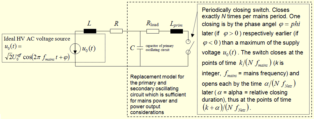
The inductance L can be the leakage inductance of a neon sign transformer or/and an external inductance.
The resistance R can be the copper resistance of the HV transformer or/and an external resistance.
The mains frequency is denoted by f_mains. The synchronously rotating spark gap is assumed to fire exactly
N times per mains period in constant time lags; thereby N>=2 is integer.
The firing angle phi denotes the phase distance between a maximum of the AC HV supply voltage and a firing event.
Thereby is phi>0 if the firing event is later in time than the maximum of the voltage, and phi<0
if the firing event is earlier. The relative spark duration (=closing duration) is denoted by α=alpha, thus the quotient between
the duration of a spark and the time interval between the beginnings of two consecutive sparks.
If you're only interested in the RMS value of the mains current and in the real and apparent power, the following
replacement model can be used approximately in both configurations (if the configuration 2 is used,
L_prim of the replacement model must be set to zero and R_load must be so small that the capacitor C is discharged
nearly immediately after the closing of the switch). In both configurations the power consumption of the resistor R_load
corresponds to the sum of the powers beeing consumed by streamers and by losses of the primary and the secondary oscillating
circuits.
If actually the configuration 1 is used, it is assumed that the capacitor C in the replacement circuit
is nearly completely discharged before the switch opens, i.e. before the spark breaks off. Therefor the
resistor R_load must be sufficiently small. Further L_prim is so small that after closing of the switch
a HF oscillation occurs in the oscillating circuit consisting of C, R_load and L_prim.
The time average of the capacitor voltage over one period of this HF oscillation is zero in a good approximation.
If you're interested in the low frequency components of the current through the inductor L, you can assume in
a good approximation that the capacitor C was discharged immediately after the closing of the switch
and was short-circuited during the closing time interval of the switch. This simplification is the
basis of the following calculations.